
4 - Add Network Technology Candidates
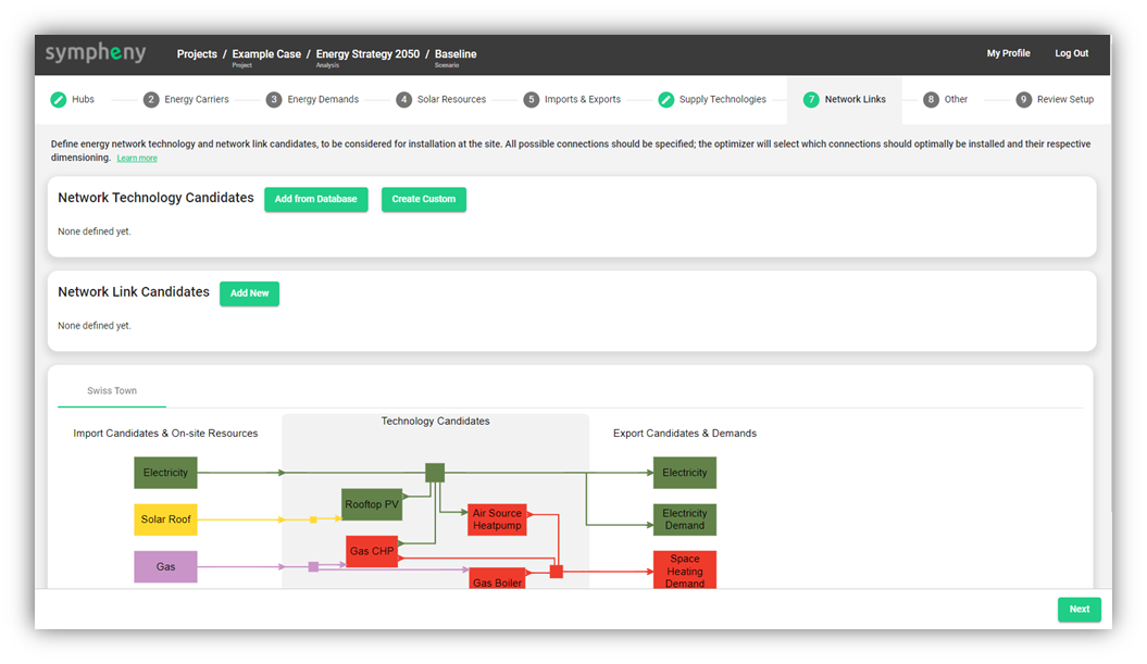
Network Technology Candidates and Network Link Candidates are used to specify the possible installation of network infrastructure between different hubs. The process is done in two steps:
First, a Network Technology needs to be specified (e.g. ‘High temperature thermal network”). This refers to the 'type’ of the Network. A Network type has specific parameters, as costs and losses per m.
Similar to conversion and storage technologies, network technology candidates can be added from a database (Add from Database) or created from scratch (Create Custom)
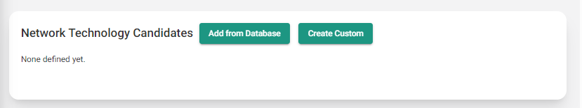
Click on one of them and fill in the parameters. Required parameters are the energy carrier being transported by this network as well as the financial lifetime.
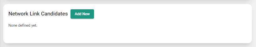
In a second step, a Network Link must be entered, e.g. a path between Hub A and Hub B. For each Network Lin the corresponding Network Technology (= type of Network) must be specified.
Here click on Add New in the Network Link Candidates section
Specify the Network Technology to apply to that link.
Enter the start and end Hub as well as the length of the connection. You can enter these values manually or directly draw on the map using the function Select Network Link on Map.
If the GIS map is not visible, you have to active the toggle Display GIS based map first.
The start point as well as the end point of the Network Link has to be within a hub (the hubs will automatically be entered in the corresponding sections). The length will also automatically be calculated based on the segment drawn. When you are done drawing, do a right click close to the end point to stop the drawing process and press Add.

Select Network Link on Map Function
A Network Link Candidate is defined between two hubs. As an example, connecting Hub A to Hub B to Hub C will require you to create two links: one link from Hub A to Hub B and one other from Hub B to Hub C.
A single Network Technology can be applied to each Network Link Candidate. For example, should want to have two potential networks (high temperature and low temperature for example) liking Hub A and Hub B, you will to defined two Network Link Candidates: a link between A and B with the Network Technology ‘high temperature network’ and another link between A and B with the Network Technology ‘low temperature network’.
Explanation of Network Technology parameters
PARAMETER | UNITS | REQUIRED? | DEFAULT | EXPLANATION |
General parameters |
|
|
|
|
Network Technology Name |
| Yes |
| The name of the technology; can be selected freely |
|
|
|
|
|
Technical parameters |
|
|
|
|
Energy Carrier |
| Yes |
| The energy carrier that can be transported with this network |
Network Loss | %/m |
| 0 | The losses as % of total capacity per meter of network length |
Maximum capacity | kW |
| Infinity | The maximum allowable capacity of the technology; only visible if Optimize is selected for "Technology capacity" in the corresponding Network link |
Minimum capacity | kW |
| 0 | The minimum allowable capacity of the technology; only visible if Optimize is selected for "Technology capacity" in the corresponding Network link |
|
|
|
|
|
Cost parameters |
|
|
|
|
Lifetime | years | Yes |
| The financial lifetime of the technology; specified in years. This is used as a basis for annualizing the investment costs of the technology. |
Fixed Investment cost | CHF/m |
| 0 | The fixed investment costs of the technology per meter (not annualized), incurred in the specified amount if the technology is installed, regardless of the sizing. |
Variable Investment Cost | CHF/kW/m |
| 0 | The variable investment costs of the technology (per kW and meter of installed capacity, not annualized) |
Fixed O&M Cost | CHF/m/year or |
| 0 | The operation and maintenance costs of the technology per meter that are incurred as a fixed amount each year if the technology is installed |
Variable O&M Cost | CHF/kW/m/year |
| 0 | The operation and maintenance costs of the technology (per kW per meter of installed capacity) that are incurred as variable amount each year depending on the installed capacity. |
|
|
|
|
|
Environmental parameters |
|
|
|
|
Fixed Embodied CO2 | kg-CO2/m |
| 0 | The embodied CO2 of the technology (i.e. the CO2 emissions incurred in the course of the technology's production and installation) |
Variable Embodied CO2 | kg-CO2/kW/m |
| 0 | The embodied CO2 of the technology (i.e. the CO2 emissions incurred in the course of the technology's production and installation); expressed per kW per meter of installed capacity |
Explanation of Network Link parameters
PARAMETER | UNITS | REQUIRED? | DEFAULT | EXPLANATION |
Optimization Options |
|
|
|
|
This Network Link must be installed |
|
| FALSE | The hubs in which the technology is forced to be installed |
|
|
|
|
|
Technical parameters |
|
|
|
|
Technology Capacity | Optimize / Specify Capacity |
| Optimize | Select whether to Optimize the capacity or specify the capacity manually (Specify Capacity) |
Capacity | kW | Yes, if "Specify Capacity" is selected above |
| The pre-specified capacity of the technology; only visible if Specify Capacity is selected above. A non-zero value of this parameter does not force the installation of the technology. Rather, it only specifies that, if the technology is installed, this is the capacity which it must assume. |
Node 1 |
| Yes |
| The hub which constitutes one of the extremes of the link. |
Node 2 |
| Yes |
| The other hub which constitutes the other extreme of the link. |
Network Technology |
| Yes |
| The network technology which can be potentially installed in this link geometry |
Length | m | Yes |
| Total length in meters of the network link |
Uni-Directional Flow? |
| Yes | No | This parameter allows to decide if the network can be operated bidirectionally or not. If the network can only be operated uni-directionally (='YES'), the Sympheny engine will choose the optimal direction (A to B OR B to A). |