
Geothermal Heat Pump
This section shows two different ways of modelling a Geothermal Heat Pump:
Modelling possibility 1: no regeneration of the ground
Modelling possibility 2: full regeneration of the ground
- Modelling possibility 1: no regeneration of the ground
In this case the modelling is similar to the Groundwater Heat Pump modelling. In this case, the regeneration potential must be calculated manually, by comparing the quantity of ‘Geothermal heat’ imported and the ‘Heat to geothermal’ exported.
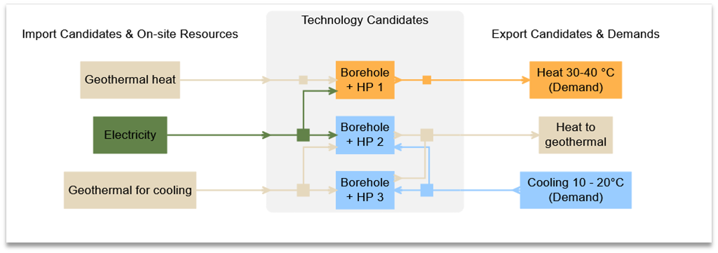
Figure 36 System Diagram for a geothermal heat pump
Set-up summary
Energy Carriers | Energy Demands | Imports | Exports | Supply technology | ||
Borehole | Borehole | Borehole | ||||
Electricity |
| X |
| Input (primary) | Input (primary) |
|
Geothermal heat |
| X |
| Input |
| Input (primary) |
Geothermal for cooling |
| X |
|
| Input |
|
Heat to geothermal |
|
|
|
| Output | Output |
Heat 30-40°C | X |
|
| Output (primary) |
| |
Cooling 10-20°C | X |
|
|
| Output (primary) | Output (primary) |
- Modelling possibility 2: full regeneration of the ground
In this case, the geothermal source is modelled as a storage. This means that only what is stored can be used, and that a 100% of the heat used must be regenerated. One of the most common ways to regenerate boreholes (considered in this example), is to have a reversible heat pump and/or free cooling when cooling demand exists.
Let’s consider a case with a cooling as well as a heating demand. A reversible brine water heat pump is installed and has the three following modes (modes settings are detailed below):
Mode 1: Heating on geothermal (heat pump)
Mode 2: Heating on ambient air (heat pump)
Mode 3: Cooling (reversible heat pump)
Set-up summary
Energy Carriers | Energy Demands | Imports | Exports | Supply technology | ||||
Brine water HP - mode 1 | Brine water HP 2 - mode 2 | Brine water HP 3 - mode 3 | HEX waste heat to geothermal | Generic Borehole | ||||
Electricity |
| X |
| Input (primary) | Input (primary) | Input (primary) |
|
|
Geothermal heat |
|
|
| Input |
|
| Output (primary) | X |
Ambient heat |
| X |
|
| Input |
|
|
|
Heat 30-40°C | X |
|
| Output (primary) | Output (primary) |
|
|
|
Cooling | X |
|
|
|
| Output (primary) |
|
|
Waste heat |
|
| X |
|
| Output | Input (primary) |
|
Set-up Implementation
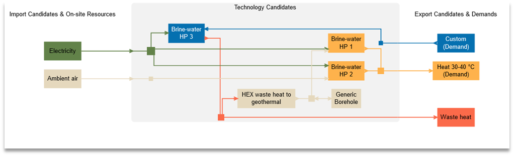
Figure 37 System diagram for a geothermal heat pump with full regeneration of the ground
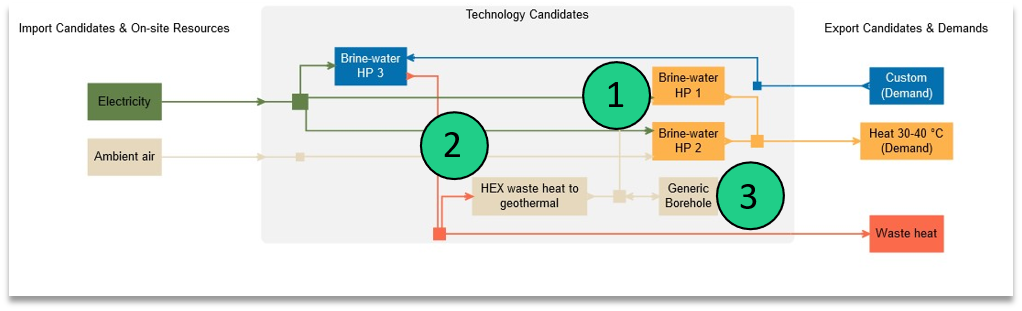
Figure 38 Setup implementation for a geothermal heat pump with full regeneration of the ground
In the time when heat is not available from the borehole, an additional operation mode is modeled. In this mode (HP2), heat pump uses ambient air as energy input.
Furthermore, it is not assured that the amount of waste heat (from HP3) is the same as the annual discharge of the borehole. In case when the excess waste heat needs to exit the system, it should be possible to export this energy carrier.

Figure 39 Overview of operation modes for a geothermal heat pump 2nd option
While the mode 1 of the heat pump draws heat from the borehole storage, the mode 3 combined with the HEX, allows to regenerate the borehole thermal storage. A heat exchanger is modelled additionally to inject the waste heat from heat pump to the ground when operating in mode 3.
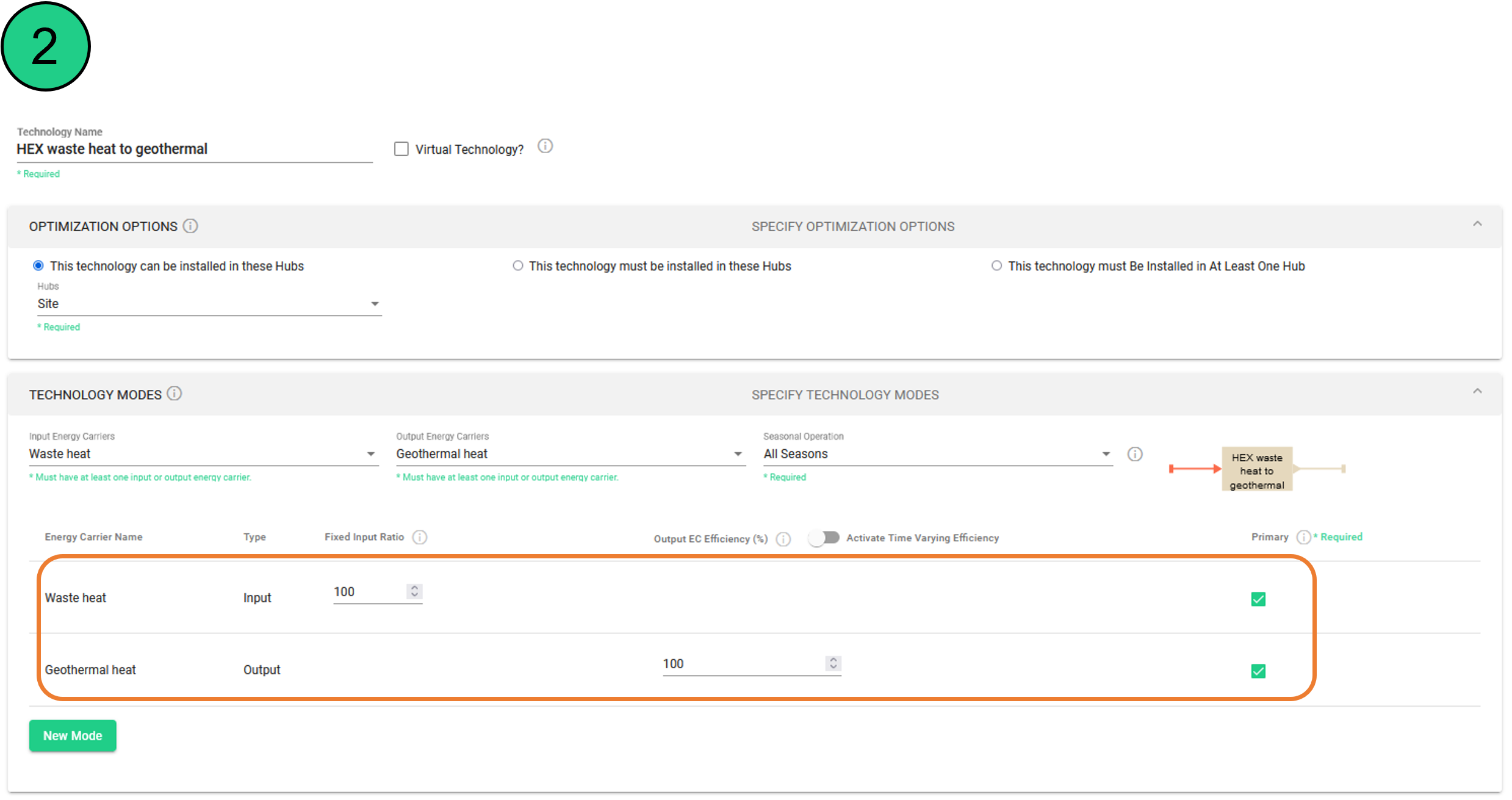
Figure 40 Modelling parameters for a HEX to regenerate the borehole thermal storage
Finally, a thermal storage technology (storing the energy carrier ‘geothermal heat’) must be added. The maximum charging / discharging rate of the storage is a crucial parameter impacting the capacity of the system when considering geothermal systems. It can be approximated through the specific extraction potential in W/m, the borehole length, and the full load hours.
The charging and discharging efficiencies must be set to 100%. Indeed, as the storage technology has the possibility to charge and discharge at the same time, this may result in losses. If the borehole is fully charged, this principle may be used to ‘unload’ the system (by charging and discharging high quantities of energy).
Example Calculation
Based on data available on the Geoportal of Berlin:
For 1 x 100m Borehole with 1’800 full load hours and a specific capacity of the ground of 40 W/m:
→ 40 W/m * 100 m * 1’800 h = 7’200 kWh = 7.2 MWh
→ Discharge capacity = 4 kW / 7200 kWh = 0.00055 = 0.055 %/h
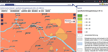
Figure 41 Geoportal map to obtain geothermal capacity for boreholes
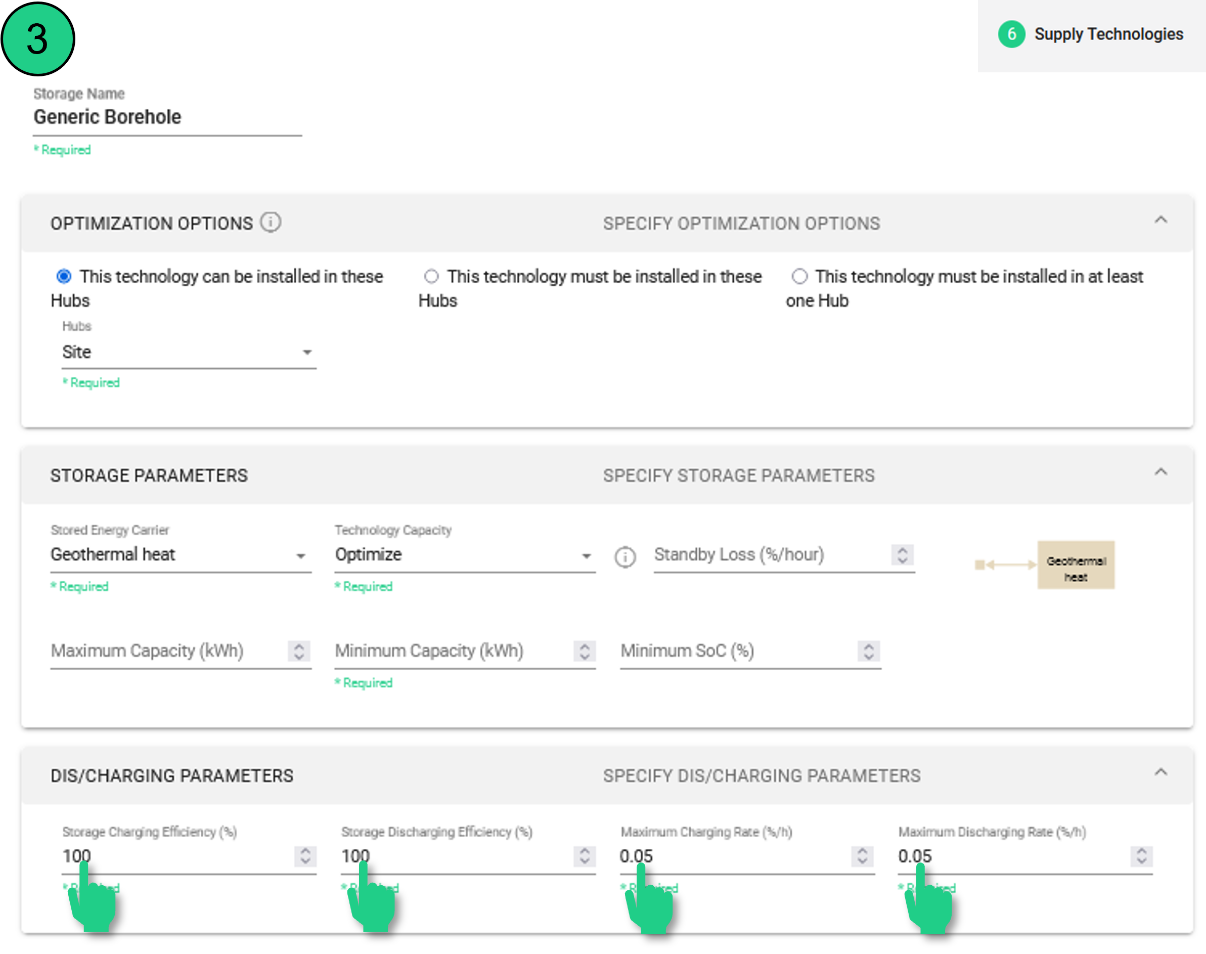
Figure 42 Charging and discharging parameters for the borehole storage
It should be noted that the energy flow to storage technologies cannot be forced. In some situations, users might wish to force a water flow that circulates through boreholes. This is a current modeling limitation and would be addressed with detailed control options in the future.
It is possible that the waste heat (from HP3) bypasses the borehole and goes to direct usage. For example, when there is a cooling demand (hence a waste heat produced from HP3) at the same time where there is a heating demand, the waste heat is directly circulated back to the brine-water heat pump (HP1) without going through the borehole storage.