
Heat Pumps
This chapter details the different ways of modelling a heat pump system within Sympheny. This includes the consideration of low-temperature sources, which availability will influence the operation of the heat pump.
This chapter starts with the modelling of basic systems (heat pump, chiller and their aggregation, reversible heat pump). In this case, we consider low temperature heat sources with unlimited availability. This hypothesis generally applies to air-source heat pump.
In a second section, different possibilities of modelling two temperature levels with a standard heat pump are shown. The chosen solution will depend on the users and on their projects. It is also possible to model all the possibilities and to let Sympheny calculate the optimal solution.
In the last section, heat pump applications where a special attention must be taken in the low temperature source are detailed: heat pump on groundwater, heat pump on geothermal heat and heat pump on wastewater.
- Standard Heat Pump
This heat pump model is working on a low-temperature source called ‘Heat Ambient’. This can be understood as being any type of source, e.g., air or water. In this simple case, the heat intake from ‘Heat Ambient’ is not limited. It is therefore more coherent to consider this technology as an air-source heat pump. In the case of a heat pump working on groundwater, river water, geothermal heat or wastewater, limitations on the availability of the low temperature source must generally be accounted for (refer to the relevant sections).
Please note that the temperature levels and COP selected here are only meant as examples.
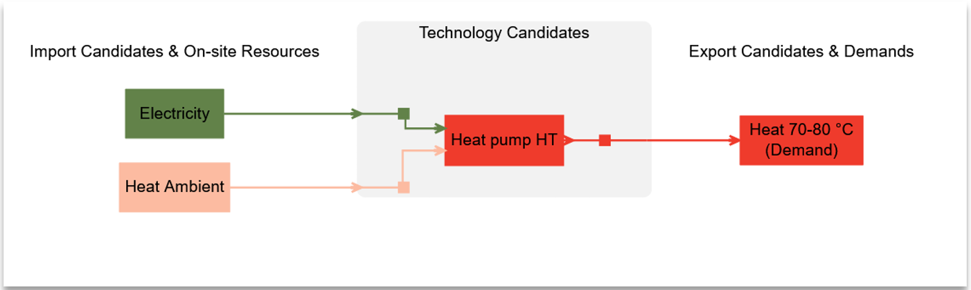
Figure 1 System diagram of a standard heat pump producing heat with electricity and ambient heat as inputs.
Video Tutorial
Set-up summary
Energy Carriers | Energy Demands | Imports | Supply technologies |
Heat pump HP | |||
Electricity |
| X | Input (primary) |
Heat ambient |
| X | Input |
Heat 70-80°C | X |
| Output (primary) |
Set-up Implementation
There are two main steps in the set-up of a simple heat pump. The first step is to define Import Candidates, and the second step is to define the Heat Pump Technology Candidate.
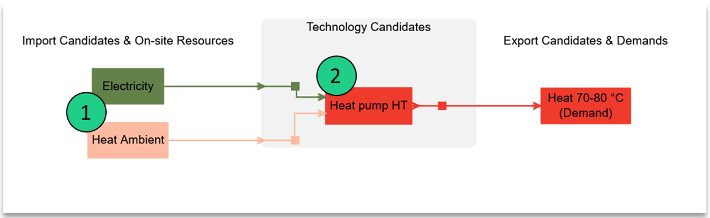
Figure 2 Set up implementation of a simple heat pump.
When defining a heat pump in Sympheny, the following steps must be done:
Defining the energy carriers necessary (as displayed in the first column of the ‘set-up summary’ table).
Defining the energy inputs of the heat pump (in this case, electricity and heat ambient) within the imports & exports tab.
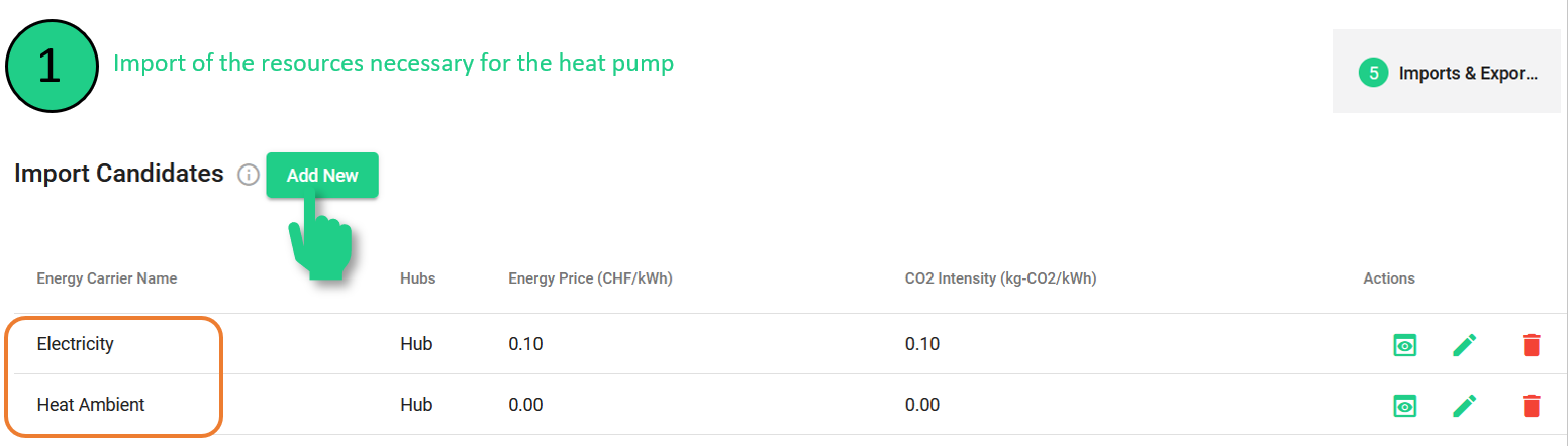
Figure 3 Import candidates for a simple heat pump with their corresponding cost and emission parameters.
In the second step, the heat pump itself is defined within the Supply Technologies tab. The COP can be flexibly adapted by the user as well as the input ratios.
It is important to make sure that the correct primary input is selected (electricity in the case of a heat pump). Indeed, the efficiency of the output is calculated based on the primary input.
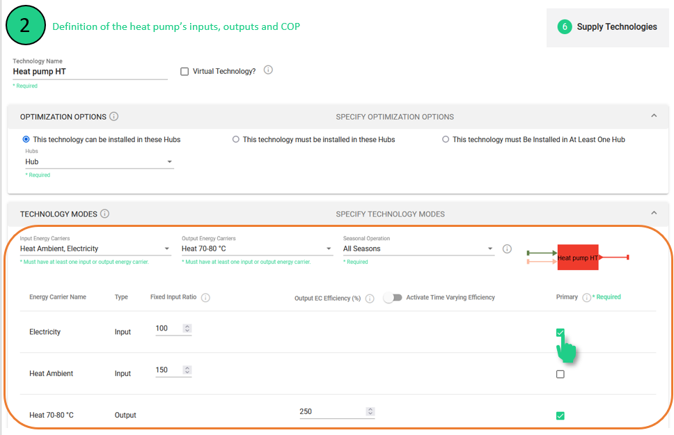
Figure 4 Definition of a heat pump’s inputs, outputs, and COP.
Optionally, for a more detailed modelling, the output efficiency can be defined with monthly efficiencies, by activating the time-varying efficiency toggle.
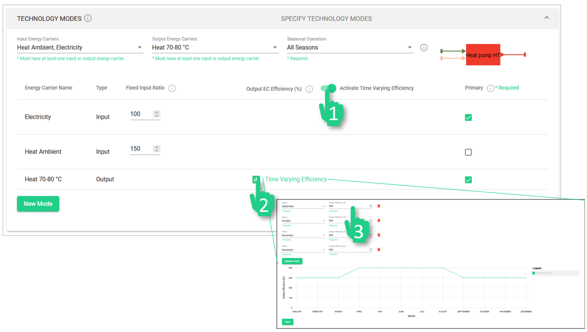
Figure 5 Activation steps of time varying efficiency.
A common pitfall is missing to fill in one of the entries: technology names, hub, checks for primary input /output, or technology lifetime (under technical parameters). If any of these entries is missing, the ‘save’ button is disabled.
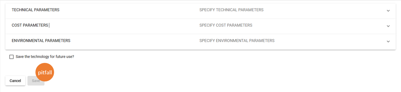
Figure 6 Common pitfall of missing entries in the conversion technology setup.
Before hitting the Save button, verify that you have all these entries set up. Per technology, there must be one primary input and one primary output (except when technology has no input, in this case, no primary input is needed).
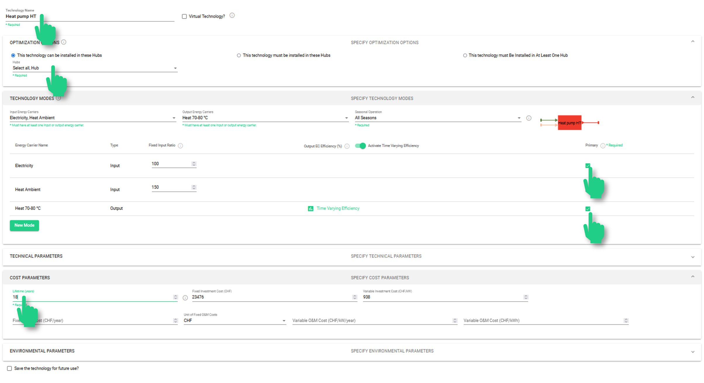
Figure 7 Final check to assure correct setup of a conversion technology.
- Modelling multiple temperature levels with a standard heat pump
The modularity of Sympheny allows the users to define their systems in a very flexible way. This section shows the different options for modelling two temperature levels with heat pumps. The standard example is the one of a residential building where space heating and domestic hot water (DHW) are required, each of them at a different temperature level: Medium Temperature (MT) for space heating and High Temperature (HT) for DHW.
Different modelling options are possible:
2 Heat pumps in parallel
2 Heat pumps in series
1 Heat pump with two modes
1 Heat pump for HT and a heat exchanger / mixer
- 2 Heat pumps in parallel
In this variant, the two heat pumps can operate totally separately. Therefore, no storage is required for the energy balance to hold. The efficiency of the “Heatpump HT” (High temperature) reflects the higher temperature delta and thus operates at a lower efficiency than “Heatpump MT“ (Medium Temperature).
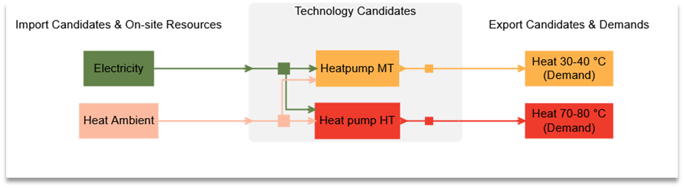
Figure 8 System diagram of two heat pumps in parallel to supply heat at two temperature levels.
Video Tutorial
- 2 Heat pumps in series
When the heat pumps are operating in series, a storage technology is required to make sure that both demands (space heating and DHW) can be supplied simultaneously without requiring a heat pump of unnecessarily large capacity. As the “Heat pump HT” is now operating on medium temperature heat as input, its COP is higher than in the previous example, 2 Heat pumps in parallel, where the heat pumps operate in parallel.
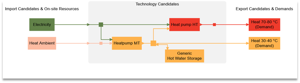
Figure 9 System diagram of two heat pumps in series with hot water storage for medium temperature heat to supply heat at two temperature levels.
Video Tutorial
- 1 Heat pump with two modes
The case of a heat pump with two modes is similar to the case of two heat pumps in parallel. By using the modes, the software will only consider the costs once (as it is the same machine). Within Sympheny’s modelling, the modes can operate simultaneously during the same hour. If a capacity limit is set, this is valid for the sum of both modes over the hour.
For a realistic operation, it is therefore strongly advised to integrate a heat storage (at least for one of the temperature levels).
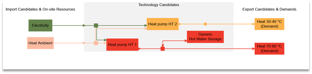
Figure 10 System diagram of one Heat pump with two modes and a Hot Water Storage for high temperature heat to supply heat at two temperature levels.
Video Tutorial
Modes are set within the definition of the supply technology. To enter a second mode, press ‘new mode’:
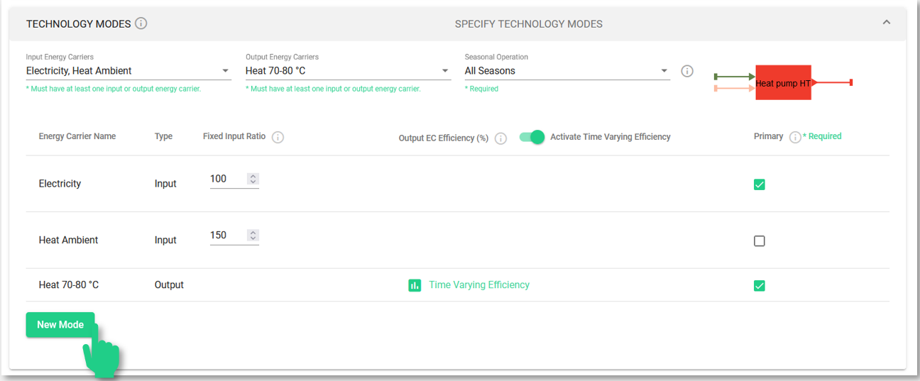
Figure 11 Setup of multiple operation modes for a conversion technology.
This will create a second field for entering the technology’s second mode of operation. In this case, both modes are very similar: the only variation is the type of output (high temperature or medium temperature heat) and the corresponding COP (entered as a percentage).
Modes of a technology can be spotted by their names in the system diagram: each mode has its mode number appended to the name of the technology (e.g. ‘Heat pump HT 1’ and ‘Heat pump HT 2’) are the operation modes of one single technology.
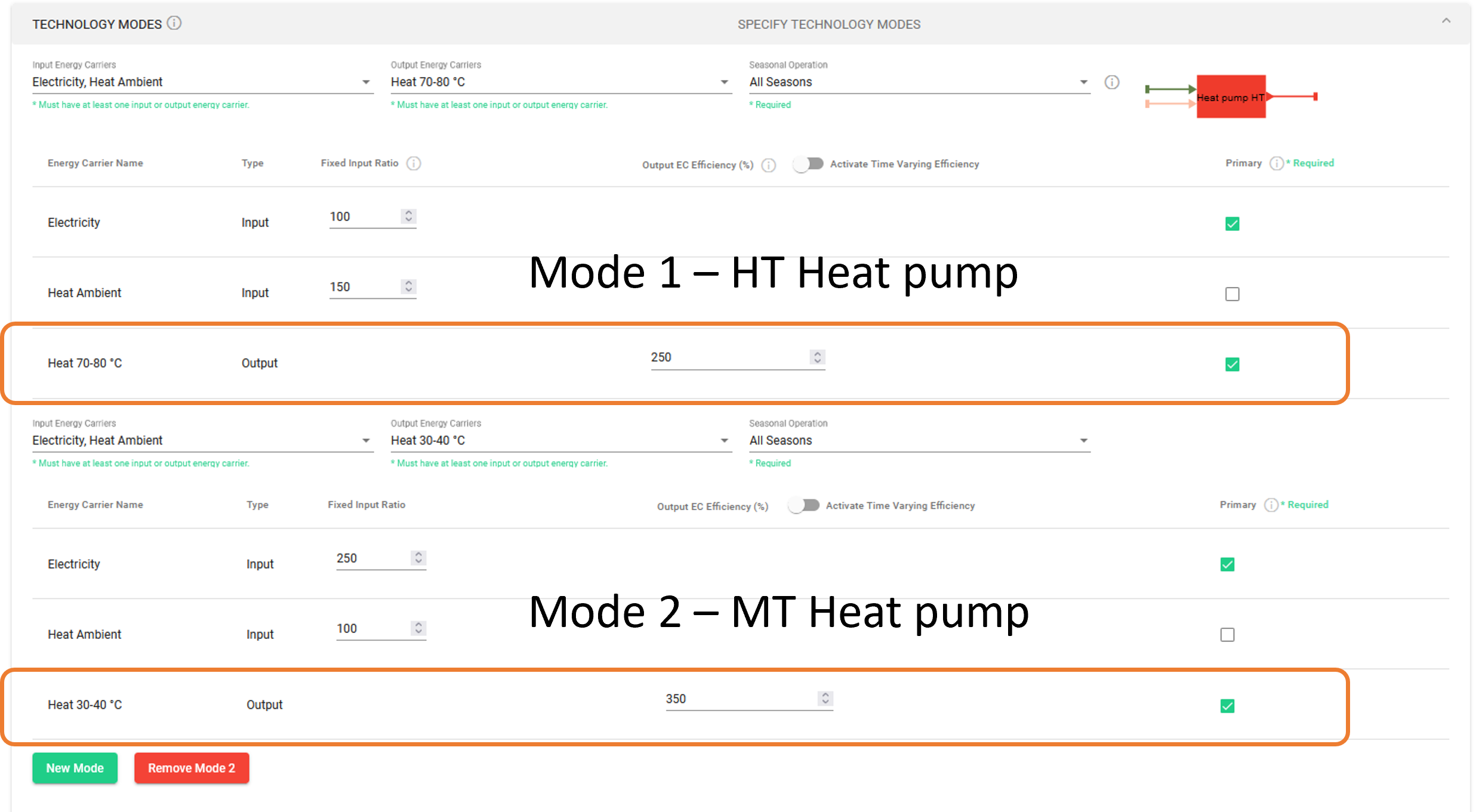
Figure 13 Definition of two operation modes for a heat pump for different temperature output.
- 1 Heat pump for HT and a heat exchanger / mixer
Finally, there is also the possibility to model a heat pump producing high temperature, which is then mixed / dissipated to another medium to create lower temperature. In this case, the production of medium temperature heat will not beneficiate from a higher COP (as was the case in the other options described above). A storage is also necessary for the energy balance to hold in case of simultaneous demand of heating and DHW.
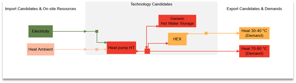
Figure 14 System diagram of a high temperature heat pump combined with a heat exchanger and thermal storage.